
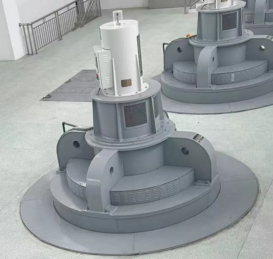
The fully adjustable shaft mixed flow pump is a medium and large diameter pump type that uses a blade angle adjuster to drive the pump blades to rotate, thereby changing the blade placement angle to achieve flow and head changes. The main conveying medium is clean water or light sewage at 0~50℃ (special media include seawater and Yellow River water). It is mainly used in the fields of water conservancy projects, irrigation, drainage and water diversion projects, and is used in many national projects such as the South-to-North Water Diversion Project and the Yangtze River to Huaihe River Diversion Project.
The blades of the shaft and mixed flow pump are spatially distorted. When the operating conditions of the pump deviate from the design point, the ratio between the circumferential speed of the inner and outer edges of the blades is destroyed, resulting in the lift generated by the blades (airfoils) at different radii no longer being equal, thereby causing the water flow in the pump to be turbulent and the water loss to increase; the farther away from the design point, the greater the degree of water flow turbulence and the greater the water loss. The axial and mixed flow pumps have low head and relatively narrow high-efficiency zone. The change of their working head will cause a significant reduction in the efficiency of the pump. Therefore, axial and mixed flow pumps generally cannot use throttling, turning and other adjustment methods to change the working performance of the operating conditions; at the same time, because the cost of speed regulation is too high, variable speed regulation is rarely used in actual operation. Since axial and mixed flow pumps have a larger hub body, it is convenient to install blades and blade connecting rod mechanisms with adjustable angles. Therefore, the working condition adjustment of axial and mixed flow pumps usually adopts variable angle adjustment, which can make the axial and mixed flow pumps operate under the most favorable working conditions.
When the upstream and downstream water level difference increases (that is, the net head increases), the blade placement angle is adjusted to a smaller value. While maintaining a relatively high efficiency, the water flow rate is appropriately reduced to prevent the motor from overloading; when the upstream and downstream water level difference decreases (that is, the net head decreases), the blade placement angle is adjusted to a larger value to fully load the motor and allow the water pump to pump more water. In short, the use of shaft and mixed flow pumps that can change the blade angle can make it operate in the most favorable working state, avoiding forced shutdown and achieving high efficiency and high water pumping.
In addition, when the unit is started, the blade placement angle can be adjusted to the minimum, which can reduce the starting load of the motor (about 1/3~2/3 of the rated power); before shutting down, the blade angle can be adjusted to a smaller value, which can reduce the backflow speed and water volume of the water flow in the pump during shutdown, and reduce the impact damage of the water flow on the equipment.
In short, the effect of blade angle adjustment is significant: ① Adjusting the angle to a smaller value makes it easier to start and shut down; ② Adjusting the angle to a larger value increases the flow rate; ③ Adjusting the angle can make the pump unit run economically. It can be seen that the blade angle adjuster occupies a relatively important position in the operation and management of medium and large pumping stations.
The main body of the fully adjustable shaft mixed flow pump consists of three parts: the pump head, the regulator, and the motor.
1. Pump head
The specific speed of the fully adjustable axial mixed flow pump is 400~1600 (the conventional specific speed of the axial flow pump is 700~1600), (the conventional specific speed of the mixed flow pump is 400~800), and the general head is 0~30.6m. The pump head is mainly composed of the water inlet horn (water inlet expansion joint), rotor parts, impeller chamber parts, guide vane body, pump seat, elbow, pump shaft parts, packing parts, etc. Introduction to key components:
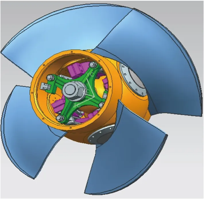
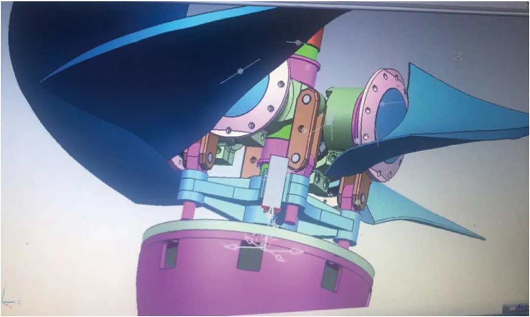
1. The rotor component is the core component in the pump head, which is composed of blades, rotor body, lower pull rod, bearing, crank arm, operating frame, connecting rod and other parts. After the overall assembly, a static balance test is performed. Among them, the blade material is preferably ZG0Cr13Ni4Mo (high hardness and good wear resistance), and CNC machining is adopted. The material of the remaining parts is generally mainly ZG.
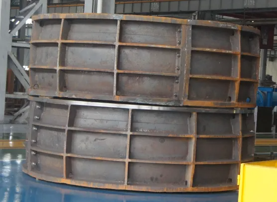
2. The impeller chamber components are integrally opened in the middle, which are tightened with bolts and positioned with conical pins. The material is preferably integral ZG, and some parts are made of ZG + lined stainless steel (this solution is complex to manufacture and prone to welding defects, so it should be avoided as much as possible).
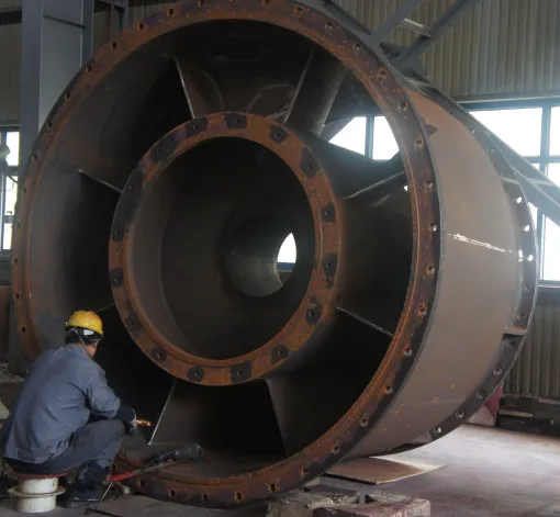
3. Guide vane body. Since the fully adjustable pump is basically a medium to large-caliber pump, the difficulty of casting, manufacturing cost and other aspects are taken into consideration. Generally, the preferred material is ZG+Q235B. The guide vane is cast in a single piece, and the shell flange is Q235B steel plate. The two are welded and then processed.
4. Pump shaft: The fully adjustable pump is generally a hollow shaft with flange structures at both ends. The material is preferably forged 45 + cladding 30Cr13. The cladding at the water guide bearing and filler is mainly to increase its hardness and improve wear resistance.

二. Introduction to the main components of the regulator
The built-in blade angle hydraulic regulator is mainly used in the market today. It mainly consists of three parts: rotating body, cover, and control display system box.
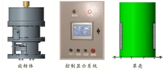
1. Rotating body: The rotating body consists of a support seat, a cylinder, a fuel tank, a hydraulic power unit, an angle sensor, a power supply slip ring, etc.
The entire rotating body is placed on the main motor shaft and rotates synchronously with the shaft. It is bolted to the top of the main motor shaft through the mounting flange.
The mounting flange is connected to the supporting seat.
The measuring point of the angle sensor is installed between the piston rod and the tie rod sleeve, and the angle sensor is installed outside the oil cylinder.
The power supply slip ring is installed and fixed on the oil tank cover, and its rotating part (rotor) rotates synchronously with the rotating body. The output end on the rotor is connected to the hydraulic power unit, pressure sensor, temperature sensor, angle sensor, and limit switch; the stator part of the power supply slip ring is connected to the stop screw on the cover, and the stator outlet is connected to the terminal in the regulator cover;
The piston rod is bolted to the water pump tie rod.
The hydraulic power unit is inside the oil tank, which provides power for the action of the oil cylinder.
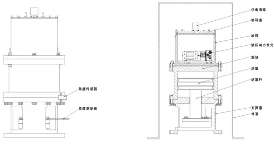
There are two lifting rings installed on the oil tank for use when lifting the regulator.
2. Cover (also called fixed body): It consists of three parts. One part is the outer cover; the second part is the cover cover; the third part is the observation window. The outer cover is installed and fixed on the top of the outer cover of the main motor to cover the rotating body.
3. Control display system box (as shown in Figure 3): It consists of PLC, touch screen, relay, contactor, DC power supply, knob, indicator light, etc. The touch screen can display the current blade angle, time, oil pressure and other parameters. The control system has two functions: local control and remote control. The two control modes are switched through the two-position knob on the control display system box (referred to as "control display box", the same below).
三. Comparison and selection of synchronous and asynchronous motors
A. Advantages and disadvantages of synchronous motors
Advantages:
1. The air gap between the rotor and the stator is large, and installation and adjustment are convenient.
2. Smooth operation and strong overload capacity.
3. The speed does not change with the load.
4. High efficiency.
5. The power factor can be advanced. Reactive power can be provided to the power grid, thereby improving the quality of the power grid. In addition, when the power factor is adjusted to 1 or close to it, the reading on the ammeter will decrease due to the reduction of the reactive component in the current, which is impossible for asynchronous motors.
Disadvantages:
1. The rotor needs to be powered by a dedicated excitation device.
2. The cost is high.
3. The maintenance is more complicated.
B. Advantages and disadvantages of asynchronous motors
Advantages:
1. The rotor does not need to be connected to other power sources.
2. Simple structure, light weight, and low cost.
3. Easy maintenance.
Disadvantages:
1. Reactive power must be drawn from the power grid, which deteriorates the quality of the power grid.
2. The air gap between the rotor and the stator is small, and installation and adjustment are inconvenient.
C. Selection of motors
The selection of motors with a rated power of 1000kW and a rated speed of 300r/min should be determined based on technical and economic comparisons according to specific conditions.
1. In the water conservancy industry, when the installed capacity is generally below 800kW, asynchronous motors are preferred, and when the installed capacity is greater than 800kW, synchronous motors tend to be selected.
2. The main difference between synchronous motors and asynchronous motors is that there is an excitation winding on the rotor, and a thyristor excitation screen needs to be configured.
3. my country's power supply department stipulates that the power factor at the user's power supply must reach 0.90 or above. Synchronous motors have a high power factor and can meet the power supply requirements; while asynchronous motors have a low power factor and cannot meet the power supply requirements, and reactive compensation is required. Therefore, pump stations equipped with asynchronous motors generally need to be equipped with reactive compensation screens.
4. The structure of synchronous motors is more complex than that of asynchronous motors. When a pump station project needs to take both power generation and phase modulation into consideration, a synchronous motor must be selected.
Fully adjustable axial mixed flow pumps are widely used in vertical units (ZLQ, HLQ, ZLQK), horizontal (inclined) units (ZWQ, ZXQ, ZGQ), and can also be used in low-lift and large-diameter LP units.
Post time: Aug-30-2024